
If you are looking for quality suppliers of hydraulic pump parts, China is a good choice. This article will help you understand 11 aspects to consider about these suppliers.
Quality hydraulic pump parts are carefully made in terms of process and material selection. The production process of high quality hydraulic pump parts includes strict control of materials and ensures that the manufacturing process meets the highest standards.
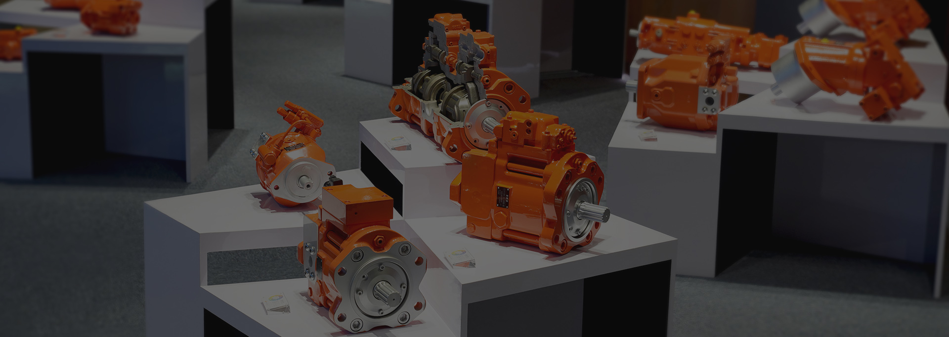
In terms of product performance, high-quality hydraulic pump parts have excellent durability and reliability. They are able to withstand high pressures, temperature variations, vibrations and shocks. In addition, these fittings also have good flow characteristics, which enable them to increase productivity.
High-quality hydraulic pump parts also have good chemical stability. They are not easily rusted and are resistant to corrosion. Thus, you can use them with confidence in various applications.
Quality hydraulic pump parts are also highly durable and reliable.
They can withstand high pressures, temperature changes, vibrations and shocks. In addition, these fittings also have good flow characteristics, which enables them to increase productivity.
In terms of the appearance of the product, quality hydraulic pump parts have a beautiful appearance. They do not deform and they maintain a good appearance even in long-term use.


Understand your needs
: Before choosing a supplier, you first need to figure out what your needs are.
Evaluate your products
: You need to evaluate the quality of your product so that you know which supplier is more suitable to choose.
Understand the supplier’s background
: Before choosing a supplier, you need to know something about it and understand its background information.
Investigate the reputation of the supplier
: Be sure to investigate the supplier’s reputation so that you can know whether it is reliable or not.
Understand the strength of the supplier
: Before choosing a supplier, you also need to know its strength.
Accept the supplier’s trial period
: Maybe you need to accept the supplier’s trial period to ensure its quality.
Ask for quotation
: Before choosing a supplier, you can ask for a quotation.
Understand how the supplier operates
: Find out how the supplier operates so you can know if they are reliable.
Consider the supplier’s services
: Before choosing a supplier, you also need to consider its services.
Ask about the supplier’s guarantees
: Before choosing a supplier, you can ask about its guarantees.
Determine the quality standards of the supplier
: Know the supplier’s quality standards so that you can determine if their products meet the requirements.
Whether you are a startup or an established company, choosing a Chinese supplier is important. If you are a startup, you can choose the quality standard of your supplier. If you are a mature business, you can choose the supplier’s service.
Finally, I hope you can find the right Chinese supplier so that you can get the best product quality and the most suitable supplier to meet your needs. SKS Hydraulic Technology is your better choice , we have more than 36 years experience in Hydraulic pump parts and hydraulic pump ,gear box . We are real manufacturer , no middle man , can hope you need service ,whatever OEM or suitable for famouse brand . welcome visit us :https://www.skshydraulic.com
We’d love to hear from you! Send us a message through the form on the right side, or email us.
